No exchanges or refunds.
All MTP/MPO Cables are custom made and have up to a 10 day lead time.
Description
Description
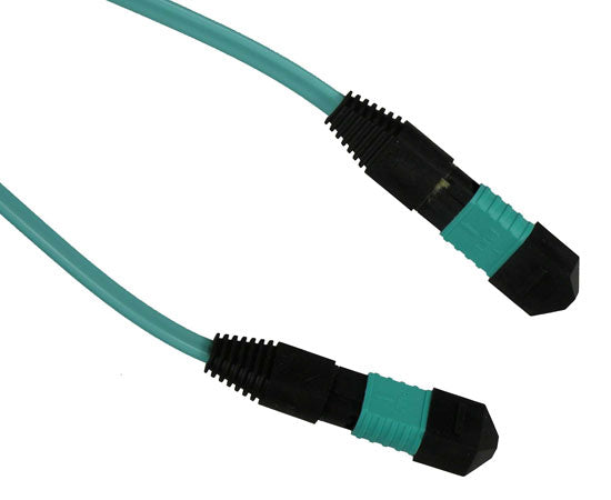
Plenum MTP®/MPO Fiber Optic Cables, Multimode 50/125 OM4, 12 Strand, Female to Female
These high speed multimode 50/125um OM4 fiber cables are terminated with MTP® fiber optic connectors on both ends (MTP-MTP). The MTP® ("Multifiber Termination Push-on") connector is a multifiber connector developed by USConec that contains up to twelve optical fibers within a single ferrule.
Each one of the MTP® cables contain 12 fibers channels in a connector smaller than most duplex connections in use today. MTP® fiber cables are designed as a high-performance version of the MPO style cable and will interconnect with MPO connectors.
Available in three polarity types:
- Type-A (Straight Through)
- Type-B (Cross, Flipped)
- Type-C (Cross Pair, Rollover)
Features
Features
- High speed plenum multimode 50/125um OM4 fiber cables
- Terminated with MTP® fiber optic connectors on both ends (MTP-MTP)
- Available in multiple lengths from 1 Meter to 50 Meters
- Method B Polarity (Cross, Flipped)
Additional Information
Additional Information
Cleaning your fiber connector end faces and components regularly is crucial for avoiding a total network failure. Ensure your optical fiber system is working properly and prevent major network issues with fiber cleaning kits, pens, fluids, and wipes.
MTP® High Density Cable
With up to 12x the density, industry experts agree that MTP® will eventually replace ST, SC, MTRJ, LC, FC and all other fiber connector types on the market today. Using MTP® connectors, a 1U rack mount patch cable can supply data for an entire 288-port switch. Combined with an MTP® cassette, this is a true plug-and-play solution.
MTP® vs. MPO
MTP® is the trademarked version of the generic MPO connector type, featuring significant advantages. Its removable housing makes the MTP® easier to rework than an MPO connector, allowing for gender changes and interferometric scanning.
The MTP® also has increased ferrule float which allows mated ferrules to remain in physical contact while connected. In contrast to the pins on an MPO connector, the MTP® has elliptical shaped guide pins to reduce wear on guide holes for the purpose of reducing debris that would cause additional loss through self contamination. Guidance is also improved.
Another advantage of the stainless steel pin design is its adherence to tight tolerances controlled during the manufacturing process. For post manufacture precision, a pin clip holds the pin guide in place. Other advantages of the pin clip is the elimination of lost pins and centering the spring force to eliminate damage caused by an un-centered spring.
Polarity Types
The polarity type determines which fibers connect from each end. With 12 fiber positions, these are the three types:
Method Type A MPO/MTP® Trunk Cables
also referred to as straight through, connects fiber 1 in the first cassette to fiber 1 in the second cassette, following this pattern through each of the 12 fiber positions—see table 1.0 below. One end is key up and the other end is in the key down position.
Table 1.0 | Polarity Method Type A

Method Type B MPO/MTP® Trunk Cables
also referred to as cross or flipped, connects fiber 1 in the first cassette to fiber 12 in the second cassette, following this pattern through each of the 12 fiber positions, with the last being 12-1—see table 1.1 below. Both ends are in the key up position.
Table 1.1 | Polarity Method Type B

Method Type-C MPO/MTP® Trunk Cables
also referred to as cross pair or rollover, connects fiber numbers in pairs, starting with 1-2 and 2-1 on one end, 11-12 and 12-11 on the other end—see table 1.2 below for all of the fiber pairings. One end is key up and the other end is in the key down position.
Table 1.2 | Polarity Method Type C

What's in the Box
What’s in the Box
- Qty 1 - MTP®/MPO Fiber Optic Cable, 12 Fiber, Multimode 50/125 OM4, Plenum, Female to Female, Method B, 1 meter length